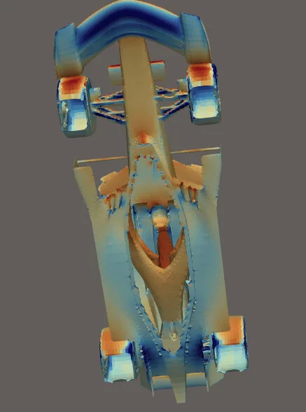
I created a new simulation project called ' Added wing (Low drag position) ': External aerodynamics on a vehicle More of my public projects can be found here .
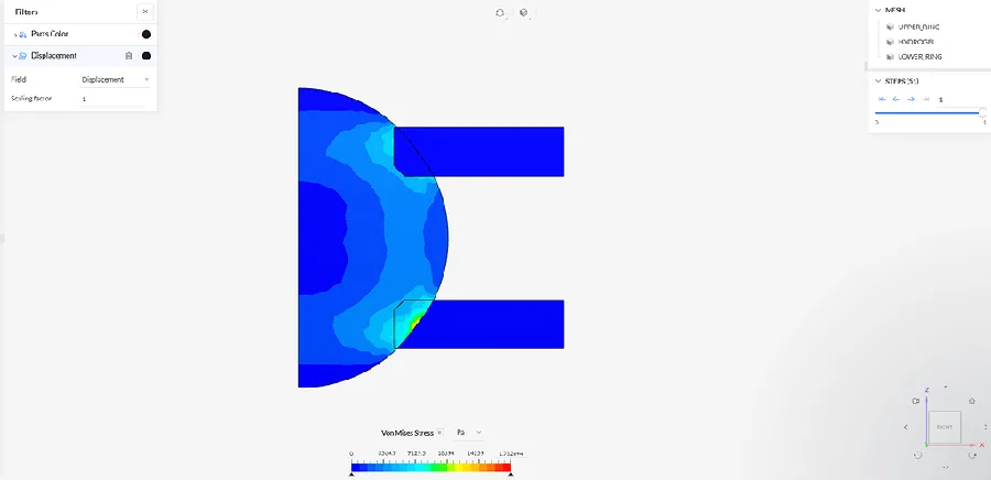
Hello, I am working on a nonlinear static simulation of a soft hydrogel sphere compressed between two annular Plexiglas rings. I have managed to obtain converged solutions for several displacement levels, but the deformation of the hydrogel is physically incorrect. The real hydrogel bead clearly bulges radially between the rings and also protrudes through the central holes of both rings when comp…
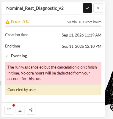
Hi SimScale Support / Community, I am experiencing a repeated issue where a nonlinear static structural simulation remains at 0% and never generates a Solver Log . I would like to determine whether this is a compute/job-start issue or whether something in the simulation setup prevents the solver from launching. Simulation setup Analysis: Nonlinear static structural Geometric nonlinearity: enabled…
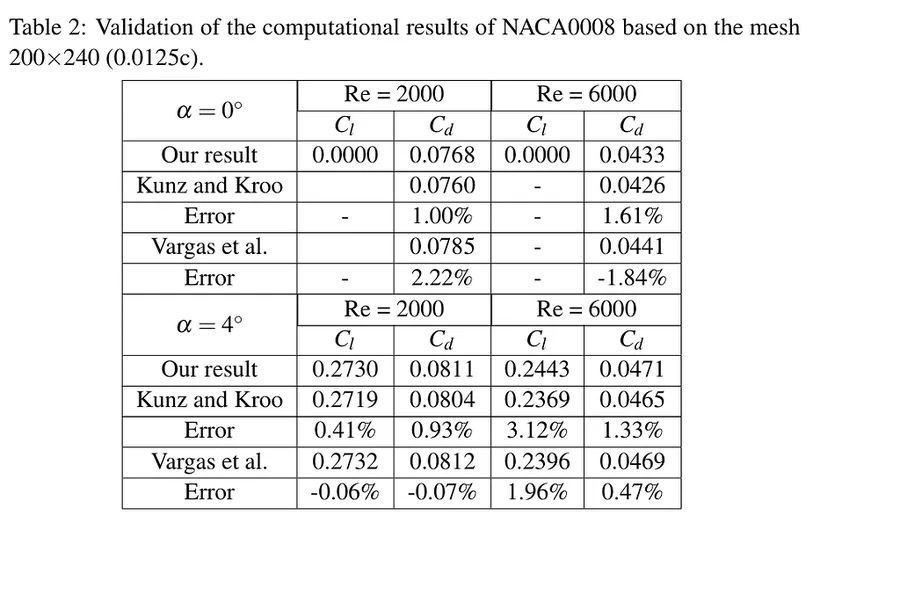
Hello everyone, I recreated the NACA0008 profile based on a dataset from UIUC and the result has a 0.2% error with the theoretical value from Vergas et al. (photo 1), when it is under an aoa of 0 degree, and Re of 2000. However, when I try with an aoa of 4 degrees, with the same model and the same meshing, the coefficients are not at all correct. I adjusted all the components by following an arti…
Error code: CqvJNURy Reference code: 3ab4c39a-8d30-4b4f-852e-849e09be8a49 I have done like 15 to 18 simulations, and i had never got any solution field. Please kindly help me regatding this. Thank you. Regards, Chinku.
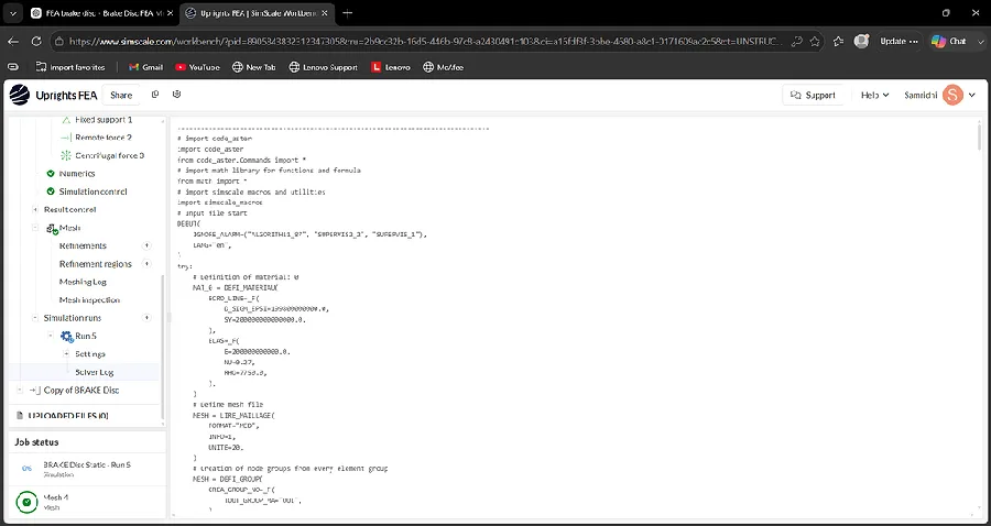
Hi, I’m performing a linear static structural analysis of a Formula Student brake disc in SimScale. My previous runs failed with machine out-of-memory errors, so I reduced the mesh and changed from 2nd-order to 1st-order elements. Current mesh: 1st-order tetrahedral elements 116,906 tetrahedra 28,843 nodes SimScale reports that the mesh meets quality criteria Current simulation: Linear static str…
I’m running a CFD research project studying F1 aerodynamics — specifically how S-Duct front-chassis geometry affects front-axle downforce loss when a car follows another through turbulent wake. This requires 6 simulation runs (baseline + dirty-air conditions at varying following distances) using the Incompressible finite-volume solver in the SimScale Community tier. My geometry (“f1_2026_cfd_v2 p…
SimScale Support Report — AMI Transient Simulation Cost/Convergence Issue Project: curved fin big pt2 (“omni wheel”) Simulation: AMI (sliding mesh) — transient run following a validated MRF steady-state sanity check Plan tier: Community 1. Project context 4-blade helical/curved Darrieus-type VAWT, rotation axis Y, 300 rpm (ω = ±31.42 rad/s), wind 5 m/s in −Z. An MRF steady-state sanity run was co…
Hello, I am currently working on an electromagnetic simulation using a transient magnetic analysis with thermal coupling . I am trying to obtain simulation results for a total simulated time of 60–300 seconds , using a time step of 0.001 s and a write interval of 1000 time steps . The simulation runs successfully for shorter simulation times (for example, 0.05 s ) and with smaller write intervals…
It is harder and it takes longer to provide support without full details.To speed up the process and quickly solve your issues this is a reminder to post as much information as you possibly can: This is a F1 CFD for me and my classmates’ school project.I just want to have a basic aerodynamic info of this model So what’s happening is that my friend adjust the rear wing angle and when I use the sam…
Hey everyone, I’m trying to run a simulation for my 70mm EDF. However, I’m not sure how to make it so that the air is actively drawn in by the EDF and accelerated out the back, just like in normal RC plane flight. Can anyone help me out with this? The link down bellow is the cad file of the edf. I cant find any good youtube tutorials, and AI like Chat gpt or gemini cant help that much too… https…
Hi SimScale Team, I accidentally deleted one of the two simulations inside my project “Uprights FEA.” The project itself is still available, but the deleted simulation was my finalized Formula Student suspension upright FEA simulation . Username: samridhi.mitblr2025@learner.manipal.edu Project: Uprights FEA Deleted: 26 August 2026, around 5:35 PM IST The deleted simulation contained my final FEA …
Hi, I have a very complex engine geometry and struggle with generating a mesh. Which settings do I best use for it? Has anyone been at this point and figured it out?
research.io
Sign up to keep scrolling
Create your feed subscriptions, save articles, keep scrolling.


 research.io